The BlasTech E-11 is one of the most well-known props from the Star Wars
universe. Based on the [Sterling submachine gun][sterling], the E-11 is iconic
as the Stormtroopers’ primary weapon throughout the original trilogy. While
finding original demilitarized Sterlings can be hard these days, great-looking
replicas can be built from PVC and metal pipes, toy blasters, or resin kits.
[sterling]: http://en.wikipedia.org/wiki/Sterling_submachine_gun
The 501st Legion [does not require blasters][weapons] in their costume
requirements, but who would take an unarmed Stormtrooper seriously? Blasters
are also required for the higher-level certifications in the [First Imperial
Stormtrooper Detachment][fisd] (FISD). The members of the FISD forums have
already built amazing replicas and thankfully have put together incredible
tutorials and suggestions for creating your own screen-accurate props and
armor, and have been my greatest resources and guide on this project.
[weapons]: http://www.501st.com/databank/Weapons_policy
[fisd]: http://www.whitearmor.net
My build is starting with a resin kit from [Doopydoo’s
Collectibles][doopydoos]. The kit isn’t perfect or complete, however, so
there’s a bit of extra work involved in modifying the kit to look more
screen-accurate. Here’s what comes in the kit:
[doopydoos]: http://www.doopydoos.com
![All resin parts in the Doopydoo’s kit][parts]
[parts]: /images/blaster/parts.jpg
Out of the box, the resin parts feel slick and powdery. Most resin makers use a
release agent to help free the cast parts from the mold, and unless it’s washed
off before shipping, is still present on the parts when they arrive. I washed
all the parts in warm, soapy water, scrubbing detailed areas with a toothbrush,
then letting them air dry.
Starting the build
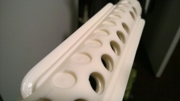
I started with drilling out the holes on the bottom of the blaster barrel.
These are covered by the folding stock when the blaster is assembled, but
they’re just visible enough that I want it to look right.
This was a bit trickier than I expected, since there’s a tiny bump in the
center of each of the spots to be drilled out. I ended up drilling a smaller
hole to get started in each one, then finished them out with a 7/16” bit to
bring them to the full width.
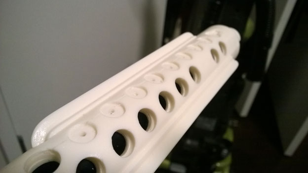
The foremost hole is actually 1/2” instead of 7/16”, and has an extra notch for
the folding stock to lock into on the actual Sterling.
![Large drilled hole on front of blaster][barreldrillfront]
[barreldrillfront]: /images/blaster/barrel-drill-front.jpg
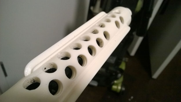
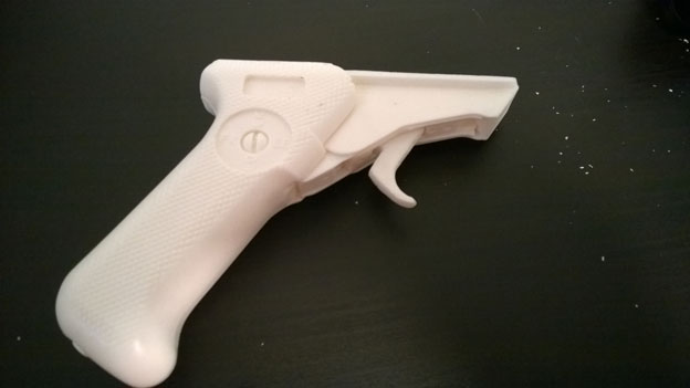
The folding stock has a bunch of these holes too, and I want to be able to
insert a wooden dowel to simulate that brace on a real folding stock. I drilled
out a couple holes, but quickly got ahead of myself and drilled with too much
force, too quickly:
![Stock broken into two pieces][stockbroken]
[stockbroken]: /images/blaster/stock-broken.jpg
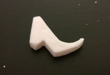
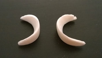
So that’s going to need to be glued back together. On the upside, I have more
room to get the Dremel into the stock to grind out the other bits, and adding
the dowel should give enough structure to keep it together when I’m finished. I
ground out the parts of the stock that would have the dowel running through it:
![Stock piece with inside ground away][stockgrind1]
![Stock piece with inside ground away][stockgrind2]
[stockgrind1]: /images/blaster/stock-grind1.jpg
[stockgrind2]: /images/blaster/stock-grind2.jpg
When I realized that the drilling and grinding is a little loud for a
weeknight, I decided to put the project away till the weekend.
Aside from the parts of the folding stock that I wanted to hollow, many of the
parts in the kit had extra bits of resin attached that left over from the
molding process. Time to use the Dremel again!
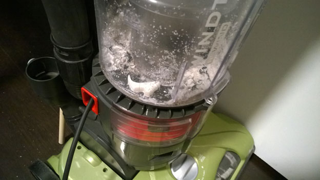
To reduce the amount of dust that ended up across the room, I set up the vacuum
cleaner next to my work area to suck away the dust as it was generated. It
wasn’t quite as effective as I’d hoped, but it helped a little.
The trigger was one of the pieces that had extra resin, with about 1/16” to the
side of the trigger, which was enough to keep the trigger from properly fitting
into its place in the grip. This might have been easier with a sander instead
of the Dremel, but in the end the piece was slimmed down pretty well:
While getting to that point, the tiny trigger piece slipped while I was
grinding and ended up in the last place I wanted it:
Twice.
But eventually the piece was finished and fit snugly inside the handle:
The guard pieces that go by the ejection port and front vent hole had some
extra material too. Those were cleaned up, but will need a little bit of
patching to clean up air bubbles from the molding process.
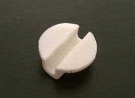
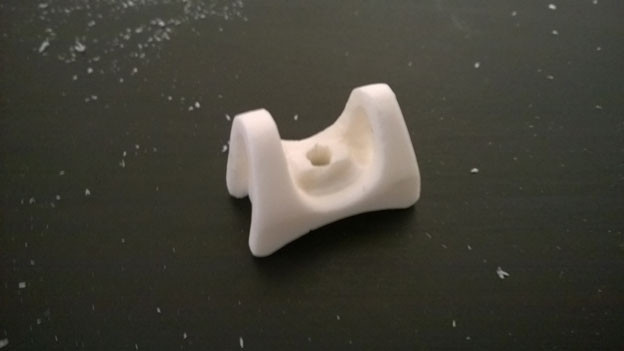
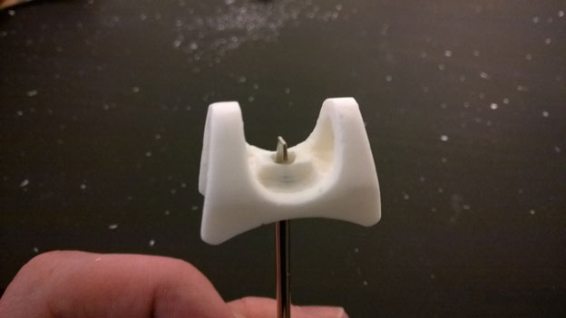
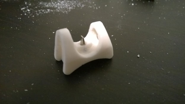
The D-ring holder that goes on the back of the blaster had a post through the
middle. Since I’m going to replace the D-ring that came with the kit, it needed
to be ground out:
Bolts
The next major bit of work was grinding down the hex bolts on the front of the
blaster. The original barrel had shapeless blob of resin where there should
have been 1/4”-20 hex bolts, so I ground out those spots as well so I can add
real bolts.
![Front of barrel with resin bolts ground away][barrel-front-drilled]
[barrel-front-drilled]: /images/blaster/barrel-front-drilled.jpg
My preferred way of placing the new bolts would be to drill out holes for them,
thread the holes, and screw them in directly, but unfortunately there isn’t
quite enough material on the barrel for this to work well. I did manage to get
one of the bolts to fit this way, but the hole wasn’t quite straight enough and
the bolt ended up crooked. In the end, I’ll need to grind out the holes and
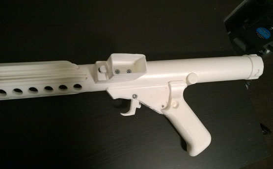
glue the bolts in. Here’s what they’ll look like when they’re finally in place:
I used fine files to clean up some of the rough spots on the blaster - seams,
bumps, and muddy-looking sections of the parts.
The bottom of the handle had another hex bolt molded into the part, so I
drilled that out and added a real one just for detail’s sake. To make room for
the head of the bolt, I used a 7/16” bit for 1/4” or so, then used a smaller
one for adding the actual bolt. This bolt is the same size as the ones on the
front of the blaster.
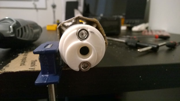
Safety Switch
A movable safety switch should be a nice detail on the finished blaster, but
the space where the switch goes is a bit more constrained than I really want it
to be since it’s so close to the handle. I won’t be able to screw the piece on
after the blaster’s painted. The best solution I could think of was setting a
small machine screw through the handle, then embedding a nut in the switch.
When the pieces are painted, I’ll be able to screw the nut on and glue on the
switch, which should be enough to leave let the switch move freely.
Drilling the hole means cutting out some of the grip texturing:
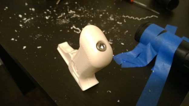
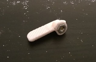
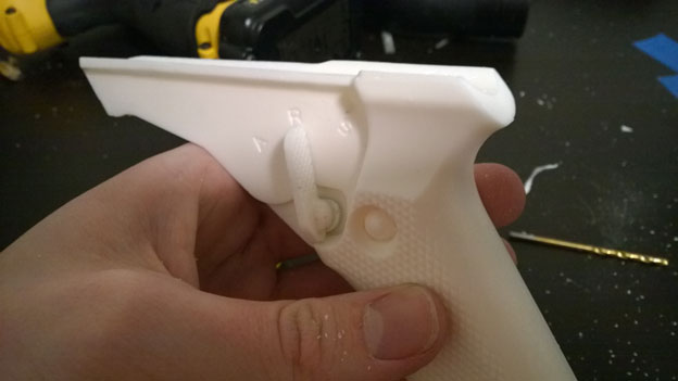
But when the nut is set in the safety switch and attached, everything works:
Trigger
I want my trigger to move too. I’ve seen a few builds that have a pen spring
behind the trigger to add motion, but setting the spring in the handle seemed
like a pain. Instead, I realized I had some magnets lying around:
These magnets have a 1/4” diameter and are 1/16” tall, and fit in the trigger
slot perfectly. To make sure this would work, I drilled a hole for one magnet
into the trigger slot, then taped another to the trigger so that the magnets’
opposite poles were facing each other:
And it worked! The magnets repel each other enough for the trigger to pop back
quickly, and the trigger action feels surprisingly smooth. With some confidence
in the final result, I drilled a hole and glued one magnet into the back of the
trigger. It is crooked, but won’t be visible on the final blaster.
The trigger itself was fastened to the handle using a short machine screw. The
holes will be filled in later. With that, I secured the handle to the barrel
using E6000 glue and some wood screws - one directly behind the magnet that
sits in the trigger, the other pointing straight up.
The big targets for this round of work were the folding stock and the magazine
housing. Finishing the folding stock was relatively simple, and I removed the
entire rod so that a 1/2” dowel can fit through the entire length.
I also worked on the front sight, grinding out some of the extra resin on the
sides, and fitting a guide in the center. While not the most accurate result, I
found a small flat head screwdriver that fits nicely in the sight piece.
The extra space in the center will be filled later.
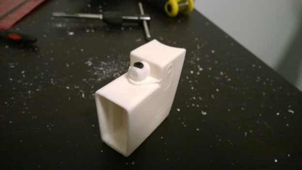
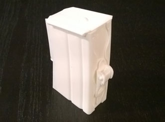
The most interesting bit of work was the magazine housing. First, I replaced
the resin set screw with a real one.
FISD member gazmosis makes resin magazines that look a thousand times better
than the one that comes from the Doopydoo’s kit, but I need to make a few
modifications to make it fit.
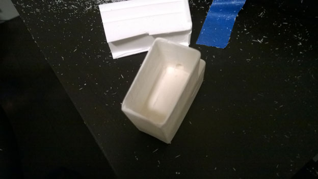
The kit includes a much smaller magazine, so the sides of the mag housing are
very thick. To get the new magazine to fit, I either needed to make it shorter
and only remove a little material from the housing, or keep the mag intact and
hollow the housing out to make room. I’d like the mag to actually look like it
was inserted into the blaster, so I decided to use a technique from another
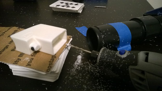
FISD member that allows me to move the housing while keeping
the Dremel in place. This way I can get the control that I need to make the
sides very thin. Here’s my setup:
The vacuum removes some of the resin bits while the Dremel stays in place. I
adjusted the number of cards in the deck to control the height of the cutting
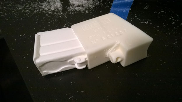
bit. It took longer than I expected, but eventually I got the magazine to fit.
I attached the mag housing to the barrel using wood screws:
More progress! I like that my “loose pieces” bag is getting more and more
empty.
“Green Stuff” is an epoxy putty that’s made of yellow and blue parts begin
to cure when mixed together. It’s a popular compound for modeling and is
good for detailed shaping, and can be sanded and carved once it’s fully
cured. I used Green Stuff to patch up air bubbles, holes from the trigger
and safety switch, the hole in the front sight, and other spots that needed
touch up work.
Scope Rail
The scope rail is the mount point for the blaster’s scope and shot counter,
and since it doesn’t come in the DoopyDoo’s kit, I had to make one on my
own. Thankfully, Billhag of the FISD made a great
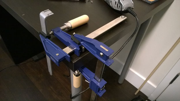
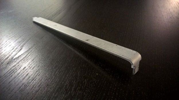
tutorial on making one from scratch. I used a 1/2” wide
and 1/16” thick steel bar, bent it, and cut it so can fit into the top hole
and rear sight. I don’t have a vise handy, so I made one out of clamps.
I still need to smooth out the rougher edges of the scope rail.
Assembly
Once I had the scope rail finished and I knew the right distance for the rear
sight, I glued it into place with E6000. I also glued on the guards around the
ejection port and front vent.
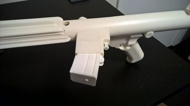
Oops. After looking at another blaster build, I realized that I’d put the
mag on housing upside down and that it should be pointing toward the front
of the blaster. I unscrewed the mag housing, re-drilled the screw holes,
and reattached it:
I also added a bit more Green Stuff to fill out some gouges in the mag
housing and stock, as well as fill in the cracks from where I glued the
stock back together.